Layer 3 - IP and Subnet Mask
Layer 3 is the layer responsible for routing packets to a destination. It also provides Quality of Service.
The Internet Protocol (IP) is the best known Layer 3 protocol, which is connection less and does not provide any flow control or error check on the packet, as it can be done by upper layers. IPv4 is the commonly used version.
Other Layer 3 protocols include: Internet Control Message Protocol (ICMP), IP Secure Encrypted Communications (IPSec).
IP Addressing
The IP Addressing implements a logical addressing scheme at Layer 3.
A network designer uses IP addresses to partition the whole network in smaller subnets to improve performance and security and make troubleshooting easier.
IP Header Structure
In picture 5.2.1, the IP header structure is presented.
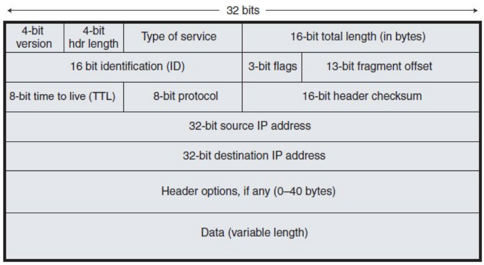 First row:
- Version: IPv4 or IPv6
- Hdr Length: length of the whole IP header, without counting the data portion
- Type of Service: here it is possible to set what kind of traffic the packet carries and use it for some router settings to improve the service (for example in VoIP communications)
Second row: needed to keep track of fragments. if a packet is too big in the link, it has to be split up into smaller packets. The default packet size on Ethernet Links is 1500 bytes MTU.
Third row:
- TTL: every time a packet goes through a router, this field is decremented by 1. When it gets to 0, the packet is dropped to avoid loops.
- Protocol: Layer 4 information type (TCP or UDP is used)
Type of Traffic
There are three main types of traffic sent from a host: Unicast (to a single destination host), Broadcast (to all the hosts on the same subnet) and Multicast (to multiple interested hosts).
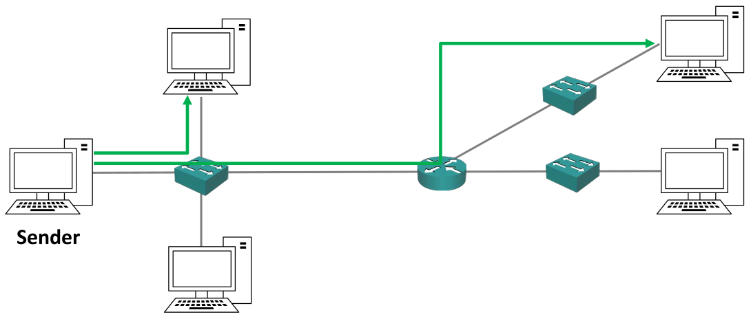
Unicast Traffic
 Unicast traffic comes from a sender and goes to one
particular host.
Unicast traffic comes from a sender and goes to one
particular host.
For multiple hosts, the sender streams out some traffic in multiple copies to all the receivers. This means that if three hosts require 1mb of packets each, the sender has to send out a total of 3mb packets to the same link.
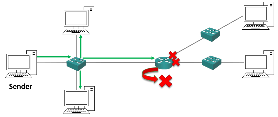
Broadcast Traffic
 With broadcast traffic the sender streams out one copy of the packet to the subnet switch, which floods the packet out to all the hosts connected to it. Routers drop this kind of traffic.
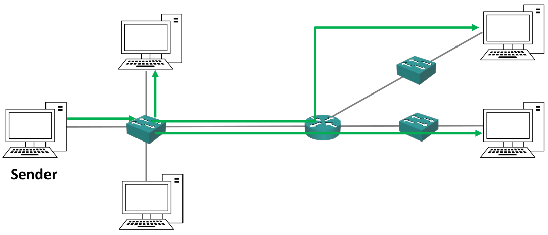
Multicast Traffic
With multicast traffic the sender streams a copy of the packet to the subnet switch, which then sends the traffic out to all the receivers that need that packet.
It avoids the traffic of multiple copies of the same packet on the same link (unlike the broadcast traffic) making it less heavy.
Unlike the broadcast traffic type, the multiple receivers are targeted.
IPv4 Addresses
An IPv4 address is a 32 bit long address written in four octets in dotted decimal format (for example: 192.168.10.15). Each octet is 8 bit long.
To find out the IP address:
- WINDOWS:
$ ipconfig
- LINUX:
$ ifconfig
$ ip route #for more info
- IOS CISCO:
# show ip interface brief
# show interface (for more info)
The IP address is usually set manually on servers, printers and network devices (like routers and switches). It is usually assigned automatically through the Dynamic Host Configuration
Protocol (DHCP) to other hosts like desktop computers.
IPv4 Address in Binary
The logical separation between different subnets is done by looking at the binary version of the IP address.
Each octet goes from 0 to 255.
For example: 192.168.10.15 corresponds to
11000000.10101000.000101010.00001111
Subnet Mask
A host can send traffic directly to another host on the same subnet using switches. If the packet has to be sent to a host outside the subnet, it has to be forwarded by a router.
The host needs to understand if the receiver is on the same subnet or if it is on a different one. To do this the subnet mask is used.
The subnet mask is a 32 bit long number that can be written in either the “four octets” notation or in the “slash” notation.
A host IP address is divided into a network portion and a host portion using the subnet mask, that defines the boundary between the two parts
Example: IP Address (IP) 192.168.10.15 and Subnet Mask (SM) 255.255.255.0
IP: 11000000.10101000.00001010.00001111
SM: 11111111.11111111.11111111.00000000
The thick borders separate the octets, and the red thick border separate the network portion (on the left) from the host portion (on the right) of the IP address.
Where there are 1s in the subnet mask, the IP address portion is the network portion, while where there are 0s in the subnet mask the IP address portion is the host portion. For this reason, 1s and 0s can’t be mixed, and the string of 1s has to be followed by the string of 0s.
The host part of the IP address can be allocated to every host in the subnet with the exception of:
- Network Address (
NA, ornetwork ID): the host part is just 0s. It identifies the subnet. In the example above the NA is192.168.10.0 - Broadcast Address (
BA): the host part is just 1s. It is the address used in broadcast communications. In the example above the BA is192.168.10.255
In the example above, the hosts can have IP addresses from 192.168.10.1 to 192.168.10.254.
The host portion specifies the individual host and must be unique on that subnet. Hosts do not have to be numbered sequentially.
Slash Notation
It is possible to write the subnet mask with the "slash notation", that is a slash symbol ( / ) followed by the number of 1s in the subnet mask.
For example: 255.255.255.0 can be written as /24, 255.255.0.0 can be written as /16.
Introduction to IPv4 vs IPv6
When IPv4 was created, it wasn’t meant for the extensive use of internet of today. Not enough space address space was created, and there is not enough addresses for everybody.
IPv6 was designed as a long term solution because it has a much bigger address space, however the short term solution consists of private IP addresses and the Network Address Translation (NAT) service.
IP Address Classes
IP addresses are assigned by the Internet Assigned Numbers Authority (IANA) for IPv4 addressing.
The classic way the IP addressing works (at least in the old days, when it was initially thought) is the following: when a company wants to communicate on internet, it gets from IANA a range of IP addresses big enough to cover the number of hosts it has, plus room to growth. Then the company allocates the IP addresses to its hosts in its offices.
To better manage the IP addressing, the address space was divided in five classes. The first three classes are assigned based on the subnet mask they are associated with, while the last two are reserved for other uses.
To identify each class, the first most significant bits (MSB) are considered.
Class A Addresses
In this class there is a very large number of hosts thanks to the /8 subnet mask.
The network address range is from 1.0.0.0 to 126.0.0.0/8. This means 126 subnets and 16,777,214 hosts per network.
The first MSB in class A is always 0.
For example: 117.0.0.0/8: 01001111.00000000.00000000.00000000
6.1.1 Class A Special Addresses
0.0.0.0 is reserved and it means “this network”. All the address range from 0.0.0.1 to 0.255.255.255 are not valid addresses.
127.0.0.0/8 is reserved for loopback addresses for testing the local computer. All the addresses from 127.0.0.1 to 127.255.255.255 can’t be assigned.
This wipes out 33,554,428 addresses.
A company doesn’t assign all hosts into a single network, because it would be bad for performance and security. It instead splits the /8 network into smaller subnets and it allocates these subnets to different offices and host types. This technique is called subnetting.
Class B Addresses
The default subnet mask for class B addresses is /16.
The network address range is from 128.0.0.0 to 191.255.0.0. This allows for 16,385 networks and 65,534 hosts per network.
The two MSB in class B are always set to 10.
For example: 131.192.0.0/16: 10000011.11000000.00000000.00000000
Class C Addresses
The default subnet mask is /24.
The network address range is from 192.0.0.0 to 223.255.255.0. This allows for 2,097,152 networks and 254 hosts per network.
The three MSB are always set to 110.
For example: 195.0.192.0/24: 11000011.00000000.11000000.00000000
Class D Addresses
Class D includes all the IP addresses form 224.0.0.0 to 239.255.255.255. They are reserved for IP multicast addresses.
They are not allocated to hosts and there is not a default subnet mask.
The four MSB are always set to 1110.
For example: 227.1.192.5: 11100011.00000001.11000000.00000101
Class E Addresses
Class E includes all the IP addresses from 240.0.0.0 to 255.255.255.255. They are classified as “experimental and reserved for future use”.
They are not allocated to hosts and there is not a default subnet mask.
The four MSB are always set to 1111.
For example: 243.1.192.10: 11110011.00000001.11000000.00001010
255.255.255.255 is the broadcast address for “this network”.
Private Addresses
There is a range of IP addresses reserved for private addressing in each class that can be assigned o hosts but that are not routable on the public internet. They were originally designed for hosts in a closed private network with no internet connectivity.
It is free, plus it improves security, as no outside host can see the hosts in a private subnet.
For class A: 10.0.0./8
For class B: 172.16.0.0/16 to 172.31.255.255
For class C: 192.168.0.0/16
Subnets and Subnetting Techniques
Classless Inter - Domain Routing (CIDR)
With classful addresses, a lot of host addresses or subnets would be wasted: for example, a company with 255 hosts would need a class B address, but this would mean that 65,534 addresses would allocated to it, wasting 65,279 addresses.
Classless Inter - Domain Routing (CIDR) was introduced in 1993 to alleviate this problem: it removes the fixed subnet mask requirements of the classes and allows them to be split into smaller networks.
For example: 175.10.10.0/20 is now allowed.
Another benefit of CIDR is that aggregate blocks of networks can now be advertised on the internet through a process called router summarization.
For example: if there is a block of networks connected to a router that goes from 175.10.0.0/24 to 175.10.255.0/24, it is now possible to advertise them through the same router just as 175.10.0.0/16, as described in the picture.
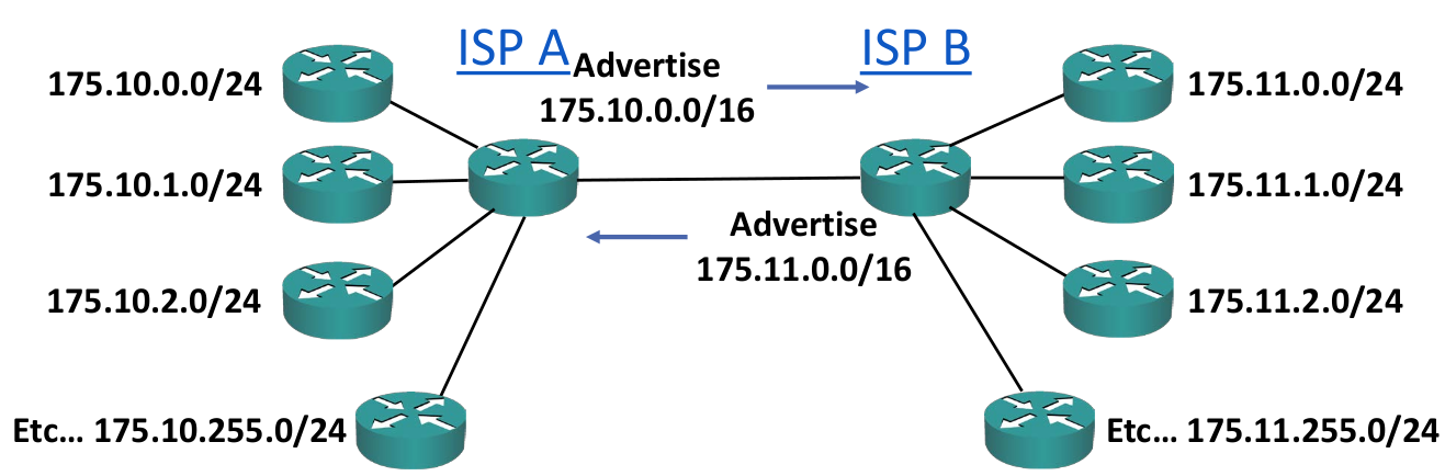
This is useful because a router doesn’t have to know about all the addresses in the internet, but just a few of them. This means that the routing table takes less space in memory, and that if an individual link goes down in a subnet, an external router doesn’t have to recalculate the whole link again. It also makes troubleshooting easier.
Subnetting
To subnet the network into smaller subnets, the separation between host and network portion of the IP address has to be moved (and can be moved just to the right side). More it moves, more subnets there will be, but with less hosts per subnet in each of them.
It is important to remember that hosts in different subnets can communicate just through a router.
To calculate the number of subnets: 2^subnet\ bits^
To calculate the number of hosts per subnet: 2^host\ bits^ - 2 (because there are also the NA and the BA)
For example:
If a /24 IP address is subnetted with a /28 subnet mask, the number of subnets will be: 2^28\ -\ 24^ = 16. The number of hosts per subnet will be 2^32\ -\ 28^ - 2 = 14.
In the old days it wasn’t possible to have network parts made of all 0s or 1s, so you were supposed to subtract 2 to the number of subnets formula too.
Because there isn’t a practical reason for it and it was a waste of addresses, it got removed.
The # ip subnet zero command on Cisco Routers overrides this limitation. It is enabled by default, therefore the default calculation on the router does not subtract two to the number of subnets formula.
/31 subnets can have just 2 addresses. It is however possible to allocate those two addresses to two hosts, breaking the standard rules of IP addrssing. This is usually done in Point - to - Point links, which do not make use of the network address and the broadcast address. This option is supported by Cisco Routers.
Steps for subnetting a network
- Find the largest segment and allocate a suitable subnet size at the start of the addressing space
- Allocate this subnet at the start of the address space
- Continue going down the list
- At the end, don’t forget the Point - to - Point links between routers
- Usually, address space for router’s loopback interfaces has to be allocated
Practice of subnetting networks is done in PDF 8.5 of the Udemy course for CCNA.
Variable Length Subnet Masking (VLSM)
Early routing protocols only supported Fixed Length Subnet
Masking (FLSM), where all the subnets had to be the same size.
All modern routing protocols support Variable Length Subnet
Masking (VLSM), which allows the sizing of the subnet differently
according to how many hosts there are per subnet.
Questions for a Correct VLSM Subnetting
- How many locations are there? How many hosts?
- What are the IP addressing requirements for each location (should different departments or host types be in different subnets)?
- What size is appropriate for each subnet, without wasting addresses, but also leaving room for growth?
Private Network Addressing
The Request for Comments 1918, or RFC 1918, is a document standard released by the Internet Engineering Task Force (IETF) that specifies the private IP address ranges which are not routable on the public internet.
An organization can use private IP addresses on their inside network, but still grant their hosts internet access by translating them to their outside public IP address through NAT.
Many hosts on the inside can share a few or a single public IP address on the outside.